Ten essentials to specify a thermal mass gas flow meter successfully
By Randy Brown, Fluid Components International
Features ipptMom and dad always said to do your homework. That was true then for school and true now for process measurement and control professionals responsible for specifying flow instrumentation.
Whether you are working on a plant upgrade, a process improvement or an expansion project, doing your homework on the application and installation will save you time and expense, and ensure success.
To specify a thermal mass flow meter correctly, there are 10 key questions you will want to understand, consider and then be able to answer. Being ready with the answers to these 10 questions will help you communicate effectively with consulting engineers, manufacturers and/or their local sales engineering team.
1. What installed accuracy is needed?
Reviewing the general accuracy statement in the manufacturer’s product literature is not enough. The installed accuracy must take into consideration the instrument’s basic accuracy capability, plus calibration, plus flow profile disturbances, and both the gas and installation temperatures and the instrument’s ability to compensate for it.
To read more articles like this, click here to download out Flow Measurement handbook.
Is an actual gas calibration needed or is equivalency acceptable?
In all cases, an actual gas calibration performed at process temperature and pressure conditions will always result in best possible accuracy for thermal mass flow meters.1 When best possible accuracy and repeatability is required, then an actual gas calibration is the solution.
In some situations, however, an actual gas calibration might not be practical, achievable or economical, and then an equivalency calibration is the only practical answer. These situations might include, but are not limited to, complex gas mixtures or for various safety reasons.
Furthermore, in applications where less accuracy and repeatability are acceptable, an equivalency calibration, using a surrogate gas (typically air), might be an acceptable, lower-cost alternative. Equivalency calibrations are theoretical, and their accuracy is the subject of much debate. When done only for purchase price savings, buyers should beware of equivalency methods. Reputable manufacturers will provide you with an expected accuracy per your specific installation conditions and the calibration process they will apply before you commit to purchase.
2. What is the gas type to be measured?
Is the gas type air, inert gas or hydrocarbon-based gas (Figure 1)? Is it a single gas or a mixture? If it is a mixture, what are the proportions of which gases? Could the gas mixture change, and, if so, by what proportions? Is the gas clean or dirty? If dirty, can you qualify and/or quantify it? Is the gas dry, moist or wet? Can you quantify the amount of moisture? Is the fluid corrosive?
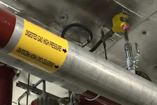
Figure 1: Knowing gas type is required to specify a thermal flow meter.
Dry, clean gases can be processed by all manufacturers. If it is a moist gas, then constant power technology has been proven to be superior. If liquid droplets or condensation conditions exist within the flow stream, then two manufacturers currently have solutions. One offers a super-
heated, 300°C [572°F] flow element to flash-off the droplets, while another manufacturer provides a mechanical shunt which prevents liquid droplets or condensate from reaching the sensors.
The measuring principle of thermal mass flow meters involves heat transfer caused by gas flow. Any moisture or condensate in the gas stream that contacts the heated sensor can cause a sudden, momentary change in the heat transfer that can result in a spiked or fluctuating reading, creating inaccurate or unstable flow measurement. Thermal flow meters using the constant ΔT (CT) method are particularly reactive to moisture droplets, while constant power (CP) method meters, because their slightly heated sensor’s temperature is elevated above the dew point of the gas are resistant to moisture’s effects.
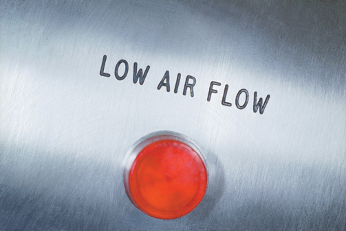
Figure 2: Know your flow range.
3. What is the required flow range?
One of the compelling features of thermal flow meters is their wide turndown capability (Figure 2). Typical turndown for most manufacturers is 100:1. Flow range capabilities are a big differentiator between suppliers and technology. Typical CT-type technology meters have less range than CP-type devices due to sensor power limitations. However, some manufacturers have special techniques to extend their measuring ranges up to 1000 fps [300 mps].
4. What is the needed response time?
While it might seem like “the faster the response the better” is the correct choice, in flow metering this might not be true at all. If the thermal flow meters will be part of a PID control loop, too fast of a response can create excessive valve responses (chatter) resulting in an inability to achieve stable flow control or premature valve failure. Conversely, if the response is too slow, the control valve action might lag by too much and desired control is not achieved. Furthermore, if the air/gas flow stream has any entrained moisture (e.g., condensation droplets), a fast-responding thermal flow meter will produce erratic, unstable readings as water droplets hit the sensors.
5. In what type and size pipe will the meter be installed?
Will the installation be in a round pipe or a rectangular duct? What is the diameter — both OD and ID — of the pipe or dimensions of the duct? If an insertion-style meter, what is the
dimension of the socket (e.g. thread-o-let), and will it be installed through a ball valve? These are important considerations for three reasons:
- Smaller diameter pipes require use of an inline or spool-piece design, rather than an insertion type.
- If an insertion-type, whether a single-point or multi-point averaging solution is recommended.
- To ensure the probe length is correct to achieve the proper insertion depth into the pipe. (In single-point types, the center of the pipe is the required installation depth) (Figure 3).
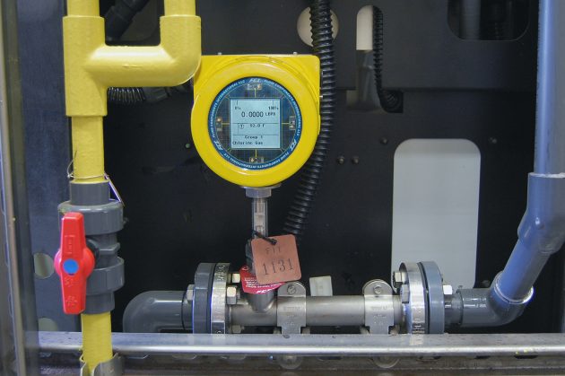
Figure 3a: Small diameter piping situations can require a different type of connection configuration.
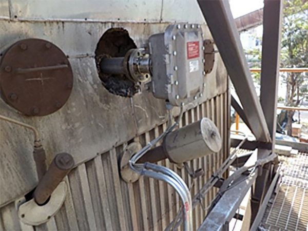
Figure 3b: Extreme example of very large diameter pipe, high temperature insulation, dusty, outdoor, above ground installation point, and in Div.1/Zone 1 type Ex location that were made clear at the beginning to ensure first-time right success.
6. How much straight run is available?
To meet their laboratory-calibrated performance specifications in their actual field installation, thermal mass flow meters require a repeatable flow profile (Figure. 4). This will naturally occur with 15d to 20d of upstream straight run and 5d to 10d of downstream straight run. These are laws of flow dynamics physics, not subject to debate. If you do not have enough straight run available, reputable manufacturers will provide information and quantification of the accuracy degradation you could expect. Furthermore, all reputable manufacturers offer some type of flow conditioning technology to produce an accurate, repeatable measurement in installations with inadequate straight run.
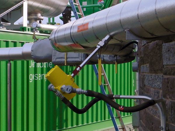
Figure 4: Consider meter flow straight-run requirements and flow disturbers.
7. What are the ambient conditions and requirements of the meter’s installation area?
Will the instrument be installed indoors, outdoors under a protective roof, or outdoors completely exposed to all weather conditions (Figure 5)? Would the installation benefit by remotely locating the electronics from the sensor element? Would a sun shield help shade the transmitter and readout? Does the instrument enclosure’s IP or NEMA-type rating meet or exceed the installation condition requirements?
Will the instrument be exposed to corrosive elements (e.g. seawater) or erosive (e.g. high-pressure or steam washdowns) conditions? Will a plastic enclosure survive? Will the paint come off or will the aluminum enclosure exhibit a patina? Will a carbon steel enclosure rust? Would service life be worth the extra investment in a stainless-steel enclosure?
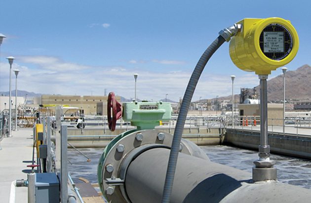
Figure 5: In outdoor, harsh desert sunlight, know the ambient conditions of your installation location.
Is the process itself running at high temperature where the instrument could be exposed to radiated heat, or does the pipe have a layer of insulation to consider? Should electronics be remotely located from the sensor element to avoid exposure to excessive heat radiating from the process? If insulated, be sure to add its depth in determining the length of the probe and the process connection.
Is the installation subject to explosive gases such that Ex class/zone approvals are required? If yes, what levels? Is the location a Div.1/Zone 1, Class I, Div.2/Zone 2, etc.? If yes, what country’s approval standards are required (e.g. FM, ATEX). Does the full instrument (sensor, electronics and enclosure) carry the matching required approval?
8. What type outputs are needed and how many?
Is a single analog output (e.g. 4-20 mA) of the flow rate adequate? If an output of the temperature is also desired, many manufacturers also provide a second analog output channel for this. Some manufacturers also offer pulse or frequency outputs to send to remote readouts or totalizers.
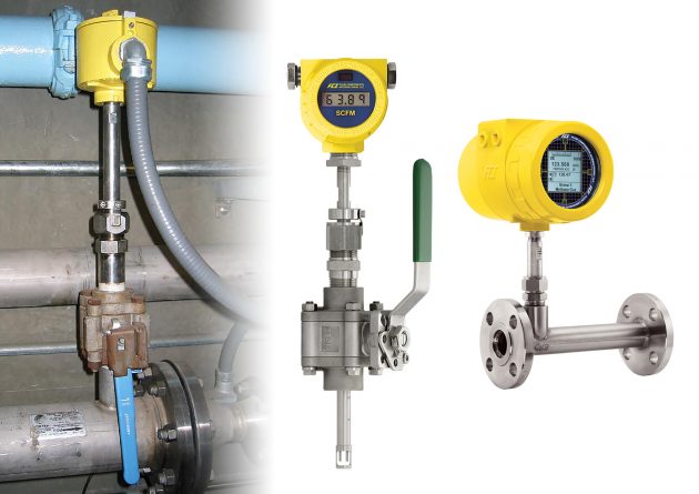
Figure 6: What is the required mechanical connection to pipe?
Or is your process tied to a bus communications-based control network requiring HART, Modbus, Foundation Fieldbus, Profibus, BACnet, EtherNetIP or other protocol? Do you require evidence of these bus comms being registered and certified to better ensure successful integration?
Is there a chance your output needs could change in the future? For example, is the plant considering migrating from traditional analog 4-20 mA signals to a digital bus? If yes, ask the flow meter manufacturer if its meter can be upgraded and, if yes, how. For the few manufacturers who offer some migration path, the means will be much different. For some it might mean returning the meter to the factory, while others might have a field upgrade kit available. Others will have both analog and digital buses already embedded and selectable by the user in the field.
9. What type of process connection will be used?
How will the flow meter be installed into the pipe and held in place (Figure 6)? Will the meter be installed in or ever need to be retracted under pressure? And if so, how much? Some manufacturers offer only a limited choice while others offer an extensive selection.
What type of fitting is required: threaded, flanged, compression type, NPT or metric? What about the required ratings? Will you need a packing gland or need to hot tap the line for installation? Would adding a ball valve be helpful for maintenance? Consider also that non-standard or special order process connections will increase the cost and extend delivery times.
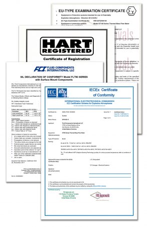
Figure 7: What certification requirements need to be met?
10. Are specific pedigrees, certifications and/or documentation required?
Often overlooked during initial considerations and application suitability are requirements for certifications and qualifications beyond the basic meter performance. This might include such things as pressure tests, certified materials and traceability, positive material identification report, and/or welding pedigree and certificates. If the thermal flow meter is to be used in a safety instrumented system (SIS), is there proof, and preferably independent verification, of SIL compliance (Figure 7). If the flow meter will be used in emissions monitoring (CEMS), does it need to have special functions or features added (e.g. calibration check routines) to comply with local regulations (e.g. U.S. EPA, European QAL1, etc.)?
Conclusion
The proper selection of any flow meter requires the specifying engineer to consider several variables. Thermal mass gas flow meters are no different. Thermal mass gas flow meters are a mainstream technology growing in popularity due to continued improvements in the technology, cost effectiveness and education on best practices. Specifying engineers prepared with answers to the 10 variables presented here will take less time to identify the best-suited product, as well as ensure first-time right installation success (Table 1).
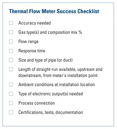
Table 1. Thermal Flow Meter Success Checklist.
1 Reference ISO 14511:2019, section 8.2; measurement of fluid flow in closed conduits – thermal mass flowmeters
All images courtesy of Fluid Components International
About the author: Randy Brown is the Director of Sales and Marketing, Fluid Components International (FCI)
eflow@fluidcomponents.com
www.FluidComponents.com
760-744-6950
Print this page
Advertisement
Ten essentials to specify a thermal mass gas flow meter successfully
Don Horne
Process West features pw featureMom and dad always said to do your homework. That was true then for school and true now for process measurement and control professionals responsible for specifying flow instrumentation.
Whether you are working on a plant upgrade, a process improvement or an expansion project, doing your homework on the application and installation will save you time and expense, and ensure success.
To specify a thermal mass flow meter correctly, there are 10 key questions you will want to understand, consider and then be able to answer. Being ready with the answers to these 10 questions will help you communicate effectively with consulting engineers, manufacturers and/or their local sales engineering team.
1. What installed accuracy is needed?
Reviewing the general accuracy statement in the manufacturer’s product literature is not enough. The installed accuracy must take into consideration the instrument’s basic accuracy capability, plus calibration, plus flow profile disturbances, and both the gas and installation temperatures and the instrument’s ability to compensate for it.
Is an actual gas calibration needed or is equivalency acceptable?
In all cases, an actual gas calibration performed at process temperature and pressure conditions will always result in best possible accuracy for thermal mass flow meters.1 When best possible accuracy and repeatability is required, then an actual gas calibration is the solution.
In some situations, however, an actual gas calibration might not be practical, achievable or economical, and then an equivalency calibration is the only practical answer. These situations might include, but are not limited to, complex gas mixtures or for various safety reasons.
To read more articles like this, click here to download out Flow Measurement handbook.
Furthermore, in applications where less accuracy and repeatability are acceptable, an equivalency calibration, using a surrogate gas (typically air), might be an acceptable, lower-cost alternative. Equivalency calibrations are theoretical, and their accuracy is the subject of much debate. When done only for purchase price savings, buyers should beware of equivalency methods. Reputable manufacturers will provide you with an expected accuracy per your specific installation conditions and the calibration process they will apply before you commit to purchase.
2. What is the gas type to be measured?
Is the gas type air, inert gas or hydrocarbon-based gas (Figure 1)? Is it a single gas or a mixture? If it is a mixture, what are the proportions of which gases? Could the gas mixture change, and, if so, by what proportions? Is the gas clean or dirty? If dirty, can you qualify and/or quantify it? Is the gas dry, moist or wet? Can you quantify the amount of moisture? Is the fluid corrosive?
Figure 1: Knowing gas type is required to specify a thermal flow meter.
Dry, clean gases can be processed by all manufacturers. If it is a moist gas, then constant power technology has been proven to be superior. If liquid droplets or condensation conditions exist within the flow stream, then two manufacturers currently have solutions. One offers a super-
heated, 300°C [572°F] flow element to flash-off the droplets, while another manufacturer provides a mechanical shunt which prevents liquid droplets or condensate from reaching the sensors.
The measuring principle of thermal mass flow meters involves heat transfer caused by gas flow. Any moisture or condensate in the gas stream that contacts the heated sensor can cause a sudden, momentary change in the heat transfer that can result in a spiked or fluctuating reading, creating inaccurate or unstable flow measurement. Thermal flow meters using the constant ΔT (CT) method are particularly reactive to moisture droplets, while constant power (CP) method meters, because their slightly heated sensor’s temperature is elevated above the dew point of the gas are resistant to moisture’s effects.
Figure 2: Know your flow range.
3. What is the required flow range?
One of the compelling features of thermal flow meters is their wide turndown capability (Figure 2). Typical turndown for most manufacturers is 100:1. Flow range capabilities are a big differentiator between suppliers and technology. Typical CT-type technology meters have less range than CP-type devices due to sensor power limitations. However, some manufacturers have special techniques to extend their measuring ranges up to 1000 fps [300 mps].
4. What is the needed response time?
While it might seem like “the faster the response the better” is the correct choice, in flow metering this might not be true at all. If the thermal flow meters will be part of a PID control loop, too fast of a response can create excessive valve responses (chatter) resulting in an inability to achieve stable flow control or premature valve failure. Conversely, if the response is too slow, the control valve action might lag by too much and desired control is not achieved. Furthermore, if the air/gas flow stream has any entrained moisture (e.g., condensation droplets), a fast-responding thermal flow meter will produce erratic, unstable readings as water droplets hit the sensors.
5. In what type and size pipe will the meter be installed?
Will the installation be in a round pipe or a rectangular duct? What is the diameter — both OD and ID — of the pipe or dimensions of the duct? If an insertion-style meter, what is the
dimension of the socket (e.g. thread-o-let), and will it be installed through a ball valve? These are important considerations for three reasons:
- Smaller diameter pipes require use of an inline or spool-piece design, rather than an insertion type.
- If an insertion-type, whether a single-point or multi-point averaging solution is recommended.
- To ensure the probe length is correct to achieve the proper insertion depth into the pipe. (In single-point types, the center of the pipe is the required installation depth) (Figure 3).
Figure 3a: Small diameter piping situations can require a different type of connection configuration.
Figure 3b: Extreme example of very large diameter pipe, high temperature insulation, dusty, outdoor, above ground installation point, and in Div.1/Zone 1 type Ex location that were made clear at the beginning to ensure first-time right success.
6. How much straight run is available?
To meet their laboratory-calibrated performance specifications in their actual field installation, thermal mass flow meters require a repeatable flow profile (Figure. 4). This will naturally occur with 15d to 20d of upstream straight run and 5d to 10d of downstream straight run. These are laws of flow dynamics physics, not subject to debate. If you do not have enough straight run available, reputable manufacturers will provide information and quantification of the accuracy degradation you could expect. Furthermore, all reputable manufacturers offer some type of flow conditioning technology to produce an accurate, repeatable measurement in installations with inadequate straight run.
Figure 4: Consider meter flow straight-run requirements and flow disturbers.
7. What are the ambient conditions and requirements of the meter’s installation area?
Will the instrument be installed indoors, outdoors under a protective roof, or outdoors completely exposed to all weather conditions (Figure 5)? Would the installation benefit by remotely locating the electronics from the sensor element? Would a sun shield help shade the transmitter and readout? Does the instrument enclosure’s IP or NEMA-type rating meet or exceed the installation condition requirements?
Will the instrument be exposed to corrosive elements (e.g. seawater) or erosive (e.g. high-pressure or steam washdowns) conditions? Will a plastic enclosure survive? Will the paint come off or will the aluminum enclosure exhibit a patina? Will a carbon steel enclosure rust? Would service life be worth the extra investment in a stainless-steel enclosure?
Figure 5: In outdoor, harsh desert sunlight, know the ambient conditions of your installation location.
Is the process itself running at high temperature where the instrument could be exposed to radiated heat, or does the pipe have a layer of insulation to consider? Should electronics be remotely located from the sensor element to avoid exposure to excessive heat radiating from the process? If insulated, be sure to add its depth in determining the length of the probe and the process connection.
Is the installation subject to explosive gases such that Ex class/zone approvals are required? If yes, what levels? Is the location a Div.1/Zone 1, Class I, Div.2/Zone 2, etc.? If yes, what country’s approval standards are required (e.g. FM, ATEX). Does the full instrument (sensor, electronics and enclosure) carry the matching required approval?
8. What type outputs are needed and how many?
Is a single analog output (e.g. 4-20 mA) of the flow rate adequate? If an output of the temperature is also desired, many manufacturers also provide a second analog output channel for this. Some manufacturers also offer pulse or frequency outputs to send to remote readouts or totalizers.
Figure 6: What is the required mechanical connection to pipe?
Or is your process tied to a bus communications-based control network requiring HART, Modbus, Foundation Fieldbus, Profibus, BACnet, EtherNetIP or other protocol? Do you require evidence of these bus comms being registered and certified to better ensure successful integration?
Is there a chance your output needs could change in the future? For example, is the plant considering migrating from traditional analog 4-20 mA signals to a digital bus? If yes, ask the flow meter manufacturer if its meter can be upgraded and, if yes, how. For the few manufacturers who offer some migration path, the means will be much different. For some it might mean returning the meter to the factory, while others might have a field upgrade kit available. Others will have both analog and digital buses already embedded and selectable by the user in the field.
9. What type of process connection will be used?
How will the flow meter be installed into the pipe and held in place (Figure 6)? Will the meter be installed in or ever need to be retracted under pressure? And if so, how much? Some manufacturers offer only a limited choice while others offer an extensive selection.
What type of fitting is required: threaded, flanged, compression type, NPT or metric? What about the required ratings? Will you need a packing gland or need to hot tap the line for installation? Would adding a ball valve be helpful for maintenance? Consider also that non-standard or special order process connections will increase the cost and extend delivery times.
Figure 7: What certification requirements need to be met?
10. Are specific pedigrees, certifications and/or documentation required?
Often overlooked during initial considerations and application suitability are requirements for certifications and qualifications beyond the basic meter performance. This might include such things as pressure tests, certified materials and traceability, positive material identification report, and/or welding pedigree and certificates. If the thermal flow meter is to be used in a safety instrumented system (SIS), is there proof, and preferably independent verification, of SIL compliance (Figure 7). If the flow meter will be used in emissions monitoring (CEMS), does it need to have special functions or features added (e.g. calibration check routines) to comply with local regulations (e.g. U.S. EPA, European QAL1, etc.)?
Conclusion
The proper selection of any flow meter requires the specifying engineer to consider several variables. Thermal mass gas flow meters are no different. Thermal mass gas flow meters are a mainstream technology growing in popularity due to continued improvements in the technology, cost effectiveness and education on best practices. Specifying engineers prepared with answers to the 10 variables presented here will take less time to identify the best-suited product, as well as ensure first-time right installation success (Table 1).
Table 1. Thermal Flow Meter Success Checklist.
1 Reference ISO 14511:2019, section 8.2; measurement of fluid flow in closed conduits – thermal mass flowmeters
All images courtesy of Fluid Components International
About the author: Randy Brown is the Director of Sales and Marketing, Fluid Components International (FCI)
760-744-6950
Print this page